Wear Rings
| Advantages |
|---|
|
Wear rings are designed to guide the piston and piston rods of power cylinders and to absorb lateral forces where they occur. They also prevent metal to metal contact between sliding parts. Wear rings are available in tape or machined rings.
An important advantage is that metallic siezure cannot occur with the correct design. The most frequently used non-metallic wear rings are filled PTFE and compounds of PTFE and fabric materials.
Wear rings are easily fitted into the closed grooves on the piston or in the glands. The number of wear rings to be used will depend on the radial forces and the permissible surface pressure of the wear ring material, in addition to the length of stroke, the diameter and other design factors.
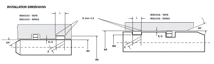
| Tape | Ring | Rod Ø C f8 |
Groove Ø D + 0.08 |
Groove Width L+0.2 |
Diametral Clearance E Max* |
Groove Ø B - 0.05 |
Cylinder Ø A H9 |
Tape | Ring |
|---|---|---|---|---|---|---|---|---|---|
| M8003C | M8103C | 8-20 | C + 3 | 3.2 | 0.4 - 1.0 | A - 3 | 10-25 | M8003A | M8103A |
| M8804C | M8104C | 15-35 | C + 5 | 4.2 | 0.5 - 2.0 | A - 5 | 20-40 | M8004A | M8104A |
| M8006C | M8106C | 20-75 | C + 5 | 6.3 | 0.5 - 2.0 | A - 5 | 25-80 | M8006A | M8106A |
| M8008C | M8108C | 30-250 | C + 5 | 8.1 | 0.5 - 2.0 | A - 5 | 40-270 | M8008A | M8108A |
| M8009C | M8109C | 50-300 | C + 5 | 9.7 | 0.5 - 2.0 | A - 5 | 60-320 | M8009A | M8109A |
| M8010C | M8110C | 50-300 | C + 5 | 10.1 | 0.5 - 2.0 | A - 5 | 60-320 | M8010A | M8110A |
| M8015C | M8115C | 120-900 | C + 5 | 15.0 | 0.5 - 2.0 | A - 5 | 120-900 | M8015A | M8115A |
| M8020C | M8120C | 200+ | C + 5 | 20.0 | 0.5 - 2.0 | A - 5 | 200+ | M8020A | M8120A |
| M8025C | M8125C | 300+ | C + 5 | 25.0 | 0.5 - 2.0 | A - 5 | 300+ | M8025A | M8125A |
| M8030C | M8130C | 300+ | C + 5 | 30.0 | 0.5 - 2.0 | A - 5 | 300+ | M8030A | M8130A |
| M8040C | M8140C | 300+ | C + 5 | 30.0 | 0.5 - 2.0 | A - 5 | 300+ | M8040A | M8140A |
| M8050C | M8150C | 300+ | C + 5 | 30.0 | 0.5 - 2.0 | A - 5 | 300+ | M8050A | M8150A |
Calculating Wear Ring Lengths and Gaps
| Calculating Wear Ring Length and Gaps | Calculating Wear Ring Widths | ||
|---|---|---|---|
| H: | F ___________ Fg x A |
||
| L | = Length | H = 0.5 | |
| C | = Rod ø | ||
| A | = Bore ø | ||
| S | = Wear Ring Thickness | where | |
| Z | = Gap between ends of installed | H | = Ring Width |
| Wear ring (mm) (see table A) | F | = Side Load (Kp) | |
| Fg | = Material Specific Load (Table B) | ||
| Then: | A | = Cylinder ø or C = Shaft ø | |
| L = 3.142 (C + S) +/- Z for Rod | |||
| L = 3.142 (A + S) +/- Z for Piston | |||
| Dia A or C mm |
Z mm up to °120C |
Z mm at 200°C |
|---|---|---|
| 50 | 0.00 | -1.00 |
| 100 | 1.00 | -1.00 |
| 200 | 2.00 | +1.50 |
| 300 | 4.50 | +4.00 |
| 600 | 10.00 | +9.00 |
| 800 | 13.00 | +13.00 |
| Code No |
Composition | Temp °C |
Material Load kp/mm2 |
Application | Coeff. Friction |
|---|---|---|---|---|---|
| 05 | PTFE/Carbon Graphite | -250 to +320 | 0.85 at 50°C 0.65 at 85°C |
Water/Air | 0.10 |
| 07 | PTFE/Bronze | -150 to + 290 | 1.60 at 50°C 0.90 at 85°C |
Hydraulic Oil | 0.08 |
| 10 | UHMW - PE | -150 to +80 | 16.5 at 50°C | Water | 0.11 |
| 99 | PTFE/Polyester | -150 to +145 | 340 at 50°C | Water, Air, Hydraulic Oil | 0.10 |
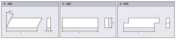
Cut Styles
Bearing capacities are given for speeds up to 1.5 m/s, Above this value, consult Moontown. Moontown wear rings can be used in all hydraulic oil media.
PTFE materials have a low coefficient of friction but also low load characteristics. They are therefore more suitable for low load applications.
Thermoplast materials have a higher friction coefficient but also high load characteristics, and can be used in high pressure.
Wear rings are made with different cuts: x for reciprocating, y for rotary and z for reciprocating or rotary movements in contaminated systems to protect the seal.
In extremely contaminated systems, consideration should be given to the use of code 99 material position inboard of the seal with any other wear ring material situated in the outboard position if required.